


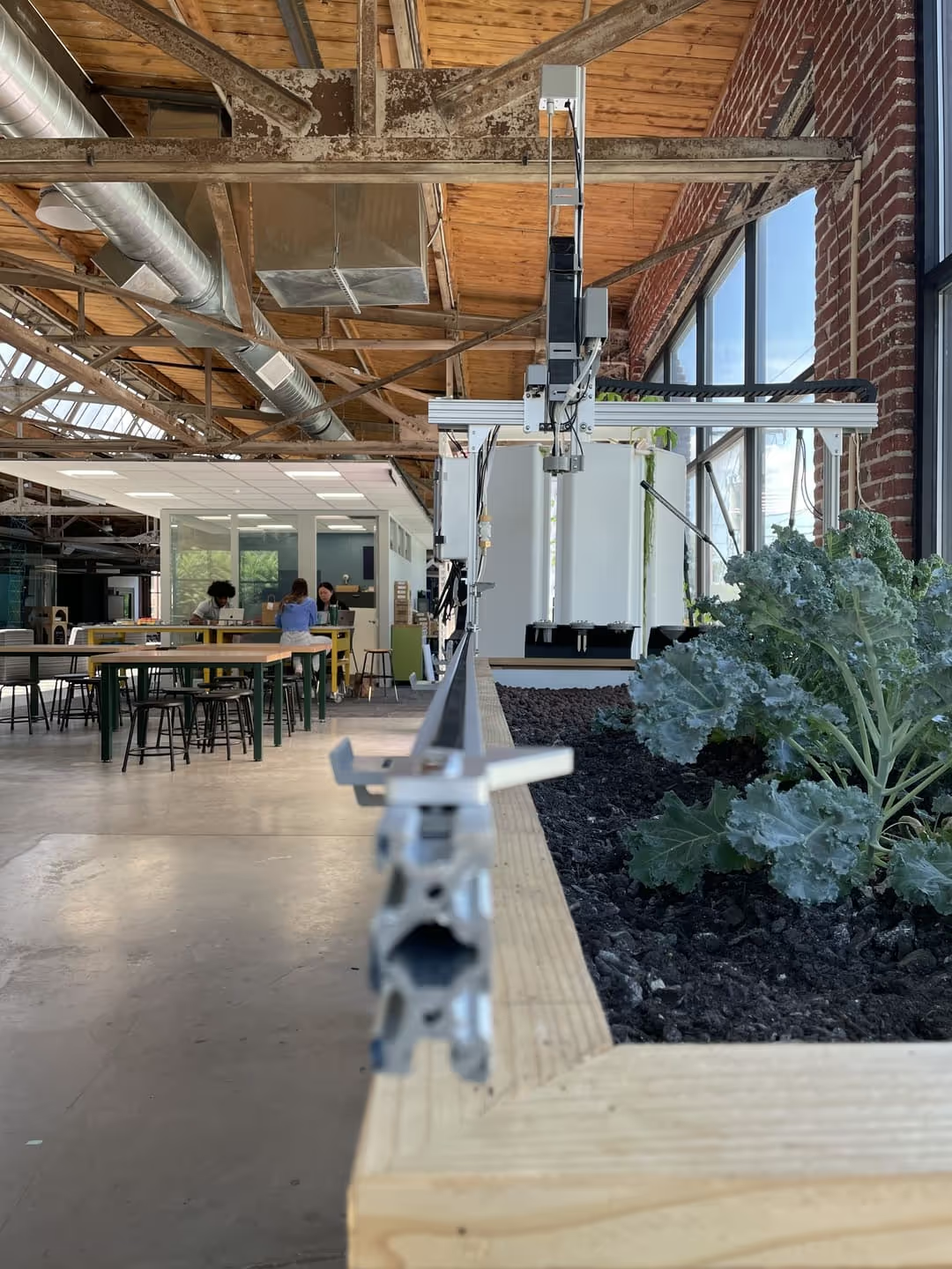
The Farmbot is one of our flagship products at Fluxspace; it combines gardening and agriculture with technology and education. After a few months of using our Farmbot, we have noticed a problem with our gantry movement system. Today, I designed and laser cut a part with the hope of overcoming our challenges.
What is a Gantry?
A gantry is a framework or structure that spans across a space and is often used to support equipment or machinery. The specific use of a gantry can vary widely across different fields; however, you can find them on our 3D printers at Fluxspace, as well as on our custom claw machine, built by our previous intern, VJ. The FarmBot uses a gantry, which allows it to move the tool head around the bed and perform tasks in various areas.
The Problem
The challenge we are encountering is a limited range of motion in our gantry system. As the head moves along the x-axis, the motors stall, causing the machine to throw an error code and halt movement. After first encountering this issue, I adjusted the eccentric nuts that hold the wheels on the x-axis t-slot rails. This reduced the pressure between the wheels and the x-axis rails and temporarily fixed the problem. However, while adjusting the wheels, I noticed that the x-axis t-slot rails were not parallel to each other. This has the potential to be the root of our problem. After double checking my assumption with measurements, I concluded that the wooden walls of the garden bed are bowing outward at the center, and because the rails are attached directly to the bed walls, the rails are forced out of alignment. As the gantry moves from its home position to the maximum x-axis position, it travels across wide and narrow spots. I believe that this is causing the stalling, binding, and excess friction, similar to what we experienced with the gantry wheels. I also think that using parallel T-slot rails would resolve our issues.
The Design Process
As I mentioned previously, I measured the distance between the x-axis rails at five locations; this way, I could truly tell if the rails were parallel or not. My findings supported my hypothesis: the rails were not parallel. However, because I measured, I not only knew that the rails were not parallel, I also discovered that the rails were misaligned by 3/8ths of an inch on either side; this data allowed me to design a precise spacer that could correct the alignment.
The Final Product
Using Beam Studio, the recommended software for our Flux Inc. laser cutters, I designed the spacer. After completing the design, I uploaded it to the laser cutter and watched it create my spacer in a matter of seconds; I repeated the cut until I had enough spacers. I decided to cut my spacer design out of 1/8th inch plywood with the plan of stacking the spacers to allow for adjustability by removing or adding spacers. Below, I have included photos of the spacer part as well as the installed solution.
Project Examples
Have a solution to this challenge you want to share? Take a photo or video of your prototype, post it on social media, and don’t forget to tag us @fluxspace_io


